I've setup a redirect to my new blog at http://blog.michaelfmcnamara.com.
Your browser should be redirected in 5 seconds!
Thanks for visiting!
Wednesday, July 2, 2008
It's moving time.
Saturday, June 28, 2008
It's time for an upgrade or two...
I've decided to make the jump... to my own domain. I'll be using GoDaddy for now along with WordPress. I'm currently in the process of migrating the content from Blogger to WordPress. Once I'm happy with the content I'll setup a redirect from Blogger to my new domain.
If you would like to have a preview try this http://blog.michaelfmcnamara.com.
 On a different note my trusty Dell 1.4Mhz Pentium 4 8200 (purchased in 2002) appears to be finally on it's last legs. So I'll need to either purchase a new machine or build a new machine from scratch. Here are the components I'm thinking of using;
- Antec Mini P180 Case
- Antec NeoPower 550 Power Supply
- ASUS P5Q LGA 775 Intel P45 Motherboard
- Intel Core 2 Duo Quad Q6600
- Corsair Dominator 4GB DDR2 1055 (PC2 8500)
- Seagate Barracuda 7200.11 500GB SATA Hard Disk
- EVGA 512-P3-N801-AR GeForce 8800GT 512MB Video Card
- Samsung 20x DVD+-R Burner SATA
- Microsoft Windows Vista 64-Bit Home Premium
I've priced these components on NewEgg and they come in just around $1,000.00. I'm trying to build a machine that isn't bleeding edge but will last the test of time. I would welcome any thoughts or suggestions.
Cheers!
Sunday, June 15, 2008
DHCP Parse Error
It would seem a great many people are running into this error so I thought I would post a quick article that would help all those looking for a solution to their problem. The Nortel i2002/i2004 (any Nortel IP phone) will return the error "DHCP parse error" if the DHCP server returns DHCP option 128 with an invalid format.
In one of my first blog posts entitled "DHCP Options (VoIP)" I outlined the DHCP options and the format that the phone expected. Kenneth quickly pointed out that I had fat-fingered the example DHCP string omitting the semicolon between the values for the primary Call Server (S1) and the secondary Call Server (S2). (I've since fixed the original post)
Here's the format the DHCP option code 128 which the IP phones expects to be returned from the DHCP server when the IP phone is configured for "Full DHCP";
Nortel-i2004-A,iii.iii.iii.iii:ppppp,aaa,rrr;iii.iii.iii.iii:ppppp,aaa,rrr.
Where the following values are;
- “Nortel-i2004-A” = Option #128 begins with this string for all Nortel IP phone sets
- “iii.iii.iii.iii” = the IP Address of the Call Server (S1 or S2)
- “ppppp” = port number for the Call Server
- “aaa” = the Action for the Server
- “rrr” = the Retry Count for the Server
The IP Address must be separated from the port number by a colon (:). The parameters for the Primary (S1) and the Secondary (S2) Call Servers are separated by a semicolon (;). The string must end a period (.).
If you are using an ISC DHCP server (this is generally included with any of the Linux distributions) you can refer to my article entitled "ISC DHCP Server (Nortel VoIP)" for information on how to setup and configure the ISC DHCP server to work with Nortel IP Telephony.
Cheers!
Network Time Protocol (NTP)
 I'm sometimes amazed at how many large organizations don't have a centralized Network Time Protocol (NTP) server setup and devices configured appropriately. When troubleshooting a problem it's vital that the timestamps in the logs for each switch, router, server and appliance match up correctly.
I'm currently using two CentOS Linux servers to provide time services to over 10,000 devices in the network. My two servers are themselves syncing up with pool.ntp.org over the Internet. With CentOS I didn't need to build the software, I only needed to install the NTP package through YUM and then configure it appropriately. It was really easy, much easier than it was say 10 years ago when you had to compile the NTP software (University of Delaware) by hand hoping you didn't run into some missing library of version mismatch with the compiler.
We would first need to install the NTP software using YUM;
[root@hostname ]# yum install ntp
We would need to start the NTP daemons;
[root@hostname ]# service ntpd start
We would need to configure the server so the NTP software would start after every reboot;
[root@hostname ]# chkconfig ntpd on
With that step done we'd have ourselves and internal NTP server which would sync itself to the Internet (default configuration file in /etc/ntp.conf) and then our internal devices would sync to it.
Here are the CLI commands for configuring the ERS 8600 switch properly;
config bootconfig tz dst-name "EDT"
config bootconfig tz name "EST"
config bootconfig tz offset-from-utc 300
config bootconfig tz dst-end M11.1.0/0200
config bootconfig tz dst-start M3.2.0/0200

config ntp server create a.b.c.d
config ntp server create a.b.c.d
config ntp server create a.b.c.d
config ntp enable true
I've add the two configuration statements for the new Daylight Saving Time changes that were enacted in 2007. Please also note that I'm in the Eastern timezone (EDT/EST) so if you're not in the Eastern timezone you would need to supplement your timezone abbreviation appropriately.
Here are the commands for an ES460,ES470,ERS4500 or ERS5500 series switch
5520-48T-PWR# config terminal
5520-48T-PWR (config)# sntp server primary a.b.c.d
5520-48T-PWR (config)# sntp server secondary a.b.c.d
5520-48T-PWR (config)# sntp enable
5520-48T-PWR (config)# exit
5520-48T-PWR#
The ERS 4500/5500 Series now supports Daylight Saving Time. This feature is NOT supported on the ES460 and ES470 switches. --CORRECTION: this feature is support on the ES460/470 as of v3.7.x software, please see update at the bottom of this post for additional information. If you wanted to configure the timezone on the ERS4500/ERS5500 switch you would use the following commands;
5520-48T-PWR>enable
5520-48T-PWR# config terminal
5520-48T-PWR (config)# clock time-zone EST -5
5520-48T-PWR (config)# clock summer-time EDT date 9 Mar 2008 2:00 2 Nov 2008 2:00 +60
5520-48T-PWR (config)# exit
5520-48T-PWR#
You can use "show sntp" and "show clock" the ERS 5500 Series switch to check out your changes;
5530-24TFD#show sntp
SNTP Status:                    Enabled
Primary server address:         10.1.20.1
Secondary server address:       10.1.20.1
Sync interval:                  24 hours
Last sync source:               10.1.20.1
Primary server sync failures:   0
Secondary server sync failures: 0
Last sync time:                 2008-06-14 14:47:31 GMT-04:00
Next sync time:                 2008-06-15 14:47:31 GMT-04:00
Current time:                   2008-06-15 13:52:24 GMT-04:00
5530-24TFD#show clock
Current SNTP time  :    2008-06-15 13:52:29 GMT-04:00
Summer time is set to:
start: 28 March 2007 at 02:00
end: 30 August 2008 at 15:00
Offset: 60 minutes. Timezone will be 'EDT'
Time Zone is set to 'EST', offset from UTC is -05:00
Hopefully this will provide a brief look into NTP,SNTP and you'll agree that it really isn't that hard to setup and configure properly.
Cheers!
Update: June 17, 2008
After posting the article above I decided I would confirm that the Daylight Saving Time feature was not available on the Nortel Ethernet Switch 460/470. I found that as of v3.7.x software the feature is supported on the switches. The configuration commands are identical to the ERS4500/ERS5500 switches. Here's an example specifically for the Eastern timezone.
470-48T>enable
470-48T#config term
Enter configuration commands, one per line.  End with CNTL/Z.
470-48T(config)#clock time-zone EST -5 00
470-48T(config)#clock summer-time EDT date 9 Mar 2008 02:00 2 Nov 2008 2:00 +60
470-48T(config)#show clock summer-time
Summer time is set to:
start: 9 March 2008 at 02:00
end: 2 November 2008 at 02:00
Offset: 60 minutes. Timezone will be 'EDT'
470-48T(config)#exit
Saturday, June 14, 2008
Multi Router Traffic Grapher & RRD
 I recently needed to share some network utilization data with some non IT folks in our organization. I produced a quick report from a dynamic HTML page that contained multiple MRTG graphs. Needless to say the graphs did most of the talking while I just answered the questions. One person commented that they didn't know we had purchased such an elaborate management and monitoring solution. In short we hadn't purchased any high-end management or monitoring solution, but we had setup Multi Router Traffic Grapher (MRTG) and Round Robin Database (RRD) both of which were written by Tobi Oetiker with contributions from many others.
I've been personally using MRTG for well over 10 years now and I've yet to find any product (commercial or open source) that comes close. These two tools work hand in hand to help me graph and chart almost any SNMP value (you can also graph non-SNMP values but you need a script or something to collect the values) on almost any device connected to the network. The obvious examples for network engineers and architects such as myself is to use MRTG/RRD to help monitor current network utilization and forecast future growth. There are other examples such as graphing the temperature of a computer room or even the amount of rainfall. There are literally hundreds of examples but I'll leave you to enjoy reading about them all from the MRTG web site.
Here are two quick examples;
Internet Link with XO (Ethernet ~ 50Mbps)

Internet Link with Level3 (Ethernet ~ 50Mbps)

In the above figures MRTG is graphing the average of ifInOctets and ifOutOctects over a 5 minute interval. As I said above you could graph almost any value you wished.
I also use MRTS by Thor Dreier to help get an idea of how much actually data is traversing a specific network or interface. When we recently installed an HP MAS (Medical Archive Solution) which was built around grid computing and virtual storage technologies we observed a 300% increase in WAN traffic as the MAS was replicating data for business continuity purposes.
I will admit that MRTG can be somewhat complicated for the fledgling network engineer. However, there are dozens of implementation guides now available on the MRTG web site, including support for running MRTG on Windows.
Cheers!
Nortel Business Secure Router 222
We recently started looking for a more cost effective VPN router for small office and home office environments. With the current price of gas over $4.13/gallon there are a lot of businesses looking to try and ease the strain by effectively utilizing telecommuting for both voice and data applications. In my next few posts I'm going to look at some different technologies that a telecommuter could potential use in the virtual office.
We're currently using the Nortel VPN Router 1010, 1050 and 1100 models for mid-size to large offices but needed a more cost effective solution for home office environments such as remote call center agents and other professionals. It also doesn't help that Nortel has manufacture discontinued the 1010, 1050 and 1100 models (the bulletin from Nortel can be viewed here). There are two approaches that we are currently looking at with respect to the remote call center agents; 1) hardware solution with VPN router and IP phone; 2) software solution with VPN client and IP softphone. In this post I'm going to discuss my impressions of the Nortel Business Secure Router 222.
Let me be honest up front and tell you that I'm no fan of the Nortel VPN 200 Series Router from which this product was born. I know from opening a Nortel VPN 221 Router that it appears as if Nortel has OEM the product from Zyxel. I'm not sure if that's still the case but the GUI of the BSR 222 looks almost identical to the VPN 221.
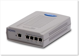 "The Business Secure Router 222, specifically designed for the small to medium business (SMB), is a converged broadband access router that provides a secure connection to the Internet via digital subscriber line (DSL) or cable modem broadband services. The Business Secure Router 222 is an advanced, feature-rich router offered at an affordable price."
We tested the BSR 222 and were very happy with the results. We provisioned multiple IPSec tunnels with Triple DES encryption to a Nortel VPN Router 1700 (V06_05.140) using Asymmetric Branch Office Tunnel (ABOT) in Aggressive mode. In our previous tests with the VPN 221 router we had all sorts of issues with the IPSec tunnels staying up in Aggressive mode. With the BSR 222 we had no such issues using the exact same profile on the VPN Router 1700 we used for the VPN 221.
We also tested connecting a Nortel i2002 over the BSR 222 and found the call quality to be excellent. While I could have paired a BES 50 with the BSR 222 to provide PoE I decided to just use a power supply on the i2002. The hardware solution seems to be a very reliable and stable solution as it probably should be. I would probably guess that a hardware solution such as this would probably cost around $800 (IP ISM, IP Phone, BSR 222). Please just remember that any VPN solution is only as stable as your broadband connection to the Internet.
The default username is "nnadmin" and the default password is "PlsChgMe!". The default IP address is 192.168.1.1 and the router can be configured from a web browser by using the URL http://192.168.1.1.
In defense of the VPN 221 router it does support a feature called "Control Ping". When this feature was configured it allowed the VPN 221 to determine if an IPSec tunnel had become disconnected from the far side. It did this by pinging an IP address that was within the tunnel network range. If the ping failed the router would essentially restart the tunnel by disconnecting it and reconnecting it. It would also keep the tunnel active on the far side preventing and keepalive issues from arising. When I configured this feature on the VPN 221 the tunnels seemed to work flawlessly. This same feature is available on the BSR 222 and it may be required if you find your tunnels bouncing up and down.
Cheers!
Friday, June 13, 2008
ERS 8648GTR duplex mismatch
 I came across a bulletin from Nortel just recently that I thought was important enough to post here in case anyone reading this has 8648GTRs installed in his/her ERS 8600 chassis. I have about 10 of them installed at multiple locations, primarily in core switches feeding large server farms and other high-speed devices. I don't believe I need to extol the pains that auto-negotiation sometimes reaps on network engineers. While modern network switches and NICs are definitely more compatible with respect to auto-negotiation, problems sometimes still arise. It would seem that a duplex mismatch on one port of the 8648GTR could potentially impact performance on up to 24 ports. Here's the text from the bulletin;
Background:
An Ethernet port can operate either in Full or Half Duplex mode. A duplex mismatch is created when using inconsistent settings for duplex mode, i.e. full duplex on the port and half duplex on the connected device (or vise versa). This situation is most likely created when using inconsistent and inappropriate settings for auto-negotiation, i.e. auto-negotiation enabled on the port and disabled on the device connected to the port (or vise versa). The duplex mismatch problem can be corrected by setting consistent duplex mode on both the port and the connected device when hard setting the duplex mode or by enabling auto-negotiation on both the port and the connected device, when using auto-negotiation.
Ethernet ports of most devices today have auto-negotiation enabled as the default setting. When a device with auto-negotiation disabled is connected to a port that has auto-negotiation enabled, the port is not able to detect the duplex setting of the connected device and falls back to half duplex thus potentially causing a duplex mismatch. A duplex mismatch will cause physical layer errors and performance degradation of the connection. Any mixture of auto-negotiation enabled on one-side and auto-negotiation disabled on the other side is an "unsupported" configuration. The setting on both sides of any connection must match for proper operation. A problem has been identified when there is a duplex mismatch on one or more ports of an 8648 GTR module. For an 8648 GTR module, a duplex mismatch may cause complete communication issues on the port with the mis-matched duplex or occasionally on the entire lane (Port 1-24 or Port 25-48) that contains the port with mismatched duplex. The module can be recovered from the situation when physically reseated, but for complete recovery the mis-configuration must also be corrected. Correcting the duplex setting configuration alone will not recover the communication loss until the module is reseated as well.
Analysis:
A duplex mismatch may cause communication loss on a port or an entire lane of an 8648 GTR module. When there is such a communication loss, the debugging commands show that the ingress stats look normal with all traffic ingressing the impacted port(s) and the MAC addresses learned in the Forwarding Database Table for the devices connected to the port(s), but no traffic egressing the port(s).
Recommendations:
Nortel recommends proper configuration of auto-negotiation whenever possible to prevent a duplex mismatch situation. To avoid a duplex mismatch, auto-negotiation must be enabled on the port as well as the device connected to that port.
You can find a copy of the bulletin in PDF format right here. Interestingly there are quite a few restrictions and issues with the 8648GTR that I should probably discuss them here when the time allows.
Nortel is also in the process of releasing v5.0 software for the Ethernet Routing Switch 8600 along with four new IO modules (cards); 8612XLRS, 8634XGRS, 8648GBRS and 8648GTRS. I hope to talk about those in the very near future.
Cheers!
Thursday, June 5, 2008
How much uptime is too much?
 A quick story for everyone...
We generally perform software upgrades on all our routers and switches twice a year. It really helps to keep our network infrastructure current and it also helps to reduced unscheduled downtime.
Last fall we decided to skip the bi-yearly maintenance because there were just too many projects on the docket. This spring we came across a very interesting issue that we had never seen in the past. We started to notice that multiple Nortel Ethernet Switch 460/470 switches/stacks were rebooting themselves all over our network. It took us a few hours to realize that every switch that had rebooted had just eclipsed approximately 500 days of uptime. All the affected switches were running FW 3.6.0.6 with SW v3.6.4.08. The switches were literally rebooting themselves in the same order in which they had been upgraded almost 500 days earlier.
I'm currently trying to confirm with Nortel that this "bug" has been removed from the 3.7.x software release.
This was one occasion where the network was just too good for itself.
Cheers!
Update: Tuesday June 10, 2008
I received a formal response from Nortel today that included the following:
Analysis of the issue :-
When the BS-470 switches reaches 497 days the system time rolls over and during this period management communication will be lost. This is caused by the use of a 32 bit counter, which when it rolls back to 0, initiates an internal software synchronization to align all timers. This is only loss of IP management and not switching functionality.
This issue still open and can be fixed by rebooting the switches before reaching the 497 day mark.
When I inquired if the problem had been resolved in the v3.7.x software release I was told it had not. It would seem that a lot of folks just don't expect switches to be running that long these days.
Cheers!
Wednesday, May 28, 2008
Succession Signaling Server - Tips Part 2
 In the first part of this two post series I gave you a small sample of some CLI diagnostic commands that are available in the Succession Signaling Server v4.5. In this post I'm going to get a little more detailed and focus on some very specific commands used for troubleshooting voice quality in a VoIP network.
For the purpose of this post we'll assume that we're using and i2004 (Phase 2) phone. These commands are available on i2002,i2004, and i2007 (Phase 2 phones only). And also available on the 1120e/1140e and 1150e (they might be available on the i2050 softphone).
With the phone online you can remotely command the phone to perform a number of basic network troubleshooting commands as well as retrieve detailed network statistics. From the CLI interface of the Succession Signaling Server you can issue the following commands;
rPing <TN | IP>, <dest>[,<count>]
This command will instruct the phone to ping an IP address.
oam> rPing 10.1.198.50, 10.1.240.40, 5
27/05/2008 18:16:34 LOG0006 VTM:
rPing Report from set (10.1.198.50) 64 bytes packets received from IP 10.1.240.40
27/05/2008 18:16:34 LOG0006 VTM:
rPing Report from set (10.1.198.50) ICMP sequence is 0
27/05/2008 18:16:34 LOG0006 VTM:
rPing Report from set (10.1.198.50) round trip time in ms: 20
27/05/2008 18:16:35 LOG0006 VTM:
rPing Report from set (10.1.198.50) 64 bytes packets received from IP 10.1.240.40
27/05/2008 18:16:35 LOG0006 VTM:
rPing Report from set (10.1.198.50) ICMP sequence is 1
27/05/2008 18:16:35 LOG0006 VTM:
rPing Report from set (10.1.198.50) round trip time in ms: 20
27/05/2008 18:16:36 LOG0006 VTM:
rPing Report from set (10.1.198.50) 64 bytes packets received from IP 10.1.240.40
27/05/2008 18:16:36 LOG0006 VTM:
rPing Report from set (10.1.198.50) ICMP sequence is 2
27/05/2008 18:16:36 LOG0006 VTM:
rPing Report from set (10.1.198.50) round trip time in ms: 20
27/05/2008 18:16:37 LOG0006 VTM:
rPing Report from set (10.1.198.50) 64 bytes packets received from IP 10.1.240.40
27/05/2008 18:16:37 LOG0006 VTM:
rPing Report from set (10.1.198.50) ICMP sequence is 3
27/05/2008 18:16:37 LOG0006 VTM:
rPing Report from set (10.1.198.50) round trip time in ms: 20
27/05/2008 18:16:38 LOG0006 VTM:
rPing Report from set (10.1.198.50) 64 bytes packets received from IP 10.1.240.40
27/05/2008 18:16:38 LOG0006 VTM:
rPing Report from set (10.1.198.50) ICMP sequence is 4
27/05/2008 18:16:38 LOG0006 VTM:
rPing Report from set (10.1.198.50) round trip time in ms: 20
27/05/2008 18:16:38 LOG0006 VTM:
rPing Report from set (10.1.198.50) 64 bytes packets received from IP 10.1.240.40
27/05/2008 18:16:38 LOG0006 VTM:
rPing Report from set (10.1.198.50) 5 packets transmitted 5 packets received, 0 packets lost
27/05/2008 18:16:38 LOG0006 VTM:
rPing Report from set (10.1.198.50) minimum round trip time in ms: 20
27/05/2008 18:16:38 LOG0006 VTM:
rPing Report from set (10.1.198.50) average round trip time in ms: 20
27/05/2008 18:16:38 LOG0006 VTM:
rPing Report from set (10.1.198.50) maximum round trip time in ms: 20
oam>
This command will instruct the phone to stop pinging.
rTraceRoute <TN | IP>, <dest>, <count>
This command will instruct the phone to trace the route of the destination address.
oam> rTraceRoute 10.1.198.50, 10.1.240.40, 3
27/05/2008 18:22:56 LOG0006 VTM: rTraceRoute Report from set (10.1.198.50): 1 -- 10.1.198.1: 0ms  0ms  0ms
27/05/2008 18:22:56 LOG0006 VTM: rTraceRoute Report from set (10.1.198.50): 2 -- 10.1.144.40: 20ms  20ms  20ms
27/05/2008 18:22:56 LOG0006 VTM: rTraceRoute Report from set (10.1.198.50): 3 -- 10.1.144.8: 20ms  20ms  20ms
27/05/2008 18:22:56 LOG0006 VTM: rTraceRoute Report from set (10.1.198.50): rTraceRoute completed !

oam>
rTraceRouteStop <TN | IP>
This command will instruct the phone to stop the trace route.
RUDPStatShow <TN |IP>[, <clear>]
This command will display the RUDP statistics from the phone.
oam> RUDPStatShow 10.1.198.50
27/05/2008 18:27:19 LOG0006 VTM:
RUDPStatShow Report from set (10.1.198.50) Number of Message Sent: 451
27/05/2008 18:27:19 LOG0006 VTM:
RUDPStatShow Report from set (10.1.198.50) Number of Message Received: 153149
27/05/2008 18:27:19 LOG0006 VTM:
RUDPStatShow Report from set (10.1.198.50) Number of Retries: 1
27/05/2008 18:27:19 LOG0006 VTM:
RUDPStatShow Report from set (10.1.198.50) Number of Resets: 0
27/05/2008 18:27:19 LOG0006 VTM:
RUDPStatShow Report from set (10.1.198.50) Uptime of Current TPS Registration: 0days 4hours 19minutes 8seconds
You can also append a value of 1 to the previous query to clear the statistics;
oam> RUDPStatShow 10.1.198.50, 1
RUDPStatShow: clear statistics after RUDPStatShow
27/05/2008 18:29:04 LOG0006 VTM:
RUDPStatShow Report from set (10.1.198.50) Number of Message Sent: 0
27/05/2008 18:29:04 LOG0006 VTM:
RUDPStatShow Report from set (10.1.198.50) Number of Message Received: 0
27/05/2008 18:29:04 LOG0006 VTM:
RUDPStatShow Report from set (10.1.198.50) Number of Retries: 0
27/05/2008 18:29:04 LOG0006 VTM:
RUDPStatShow Report from set (10.1.198.50) Number of Resets: 0
27/05/2008 18:29:04 LOG0006 VTM:
RUDPStatShow Report from set (10.1.198.50) Uptime of Current TPS Registration: 0days 4hours 20minutes 53seconds
eStatShow <TN | IP> [, <clear]
This command will display the Ethernet statistics from the phone.
oam> eStatShow 10.1.198.50
27/05/2008 18:30:55 LOG0006 VTM:
eStatShow Report from set (10.1.198.50) Duplex Mode: 1
27/05/2008 18:30:55 LOG0006 VTM:
eStatShow Report from set (10.1.198.50) Auto Negotiate Protocol Received: 0x3
27/05/2008 18:30:55 LOG0006 VTM:
eStatShow Report from set (10.1.198.50) Interface Speed: 1
27/05/2008 18:30:55 LOG0006 VTM:
eStatShow Report from set (10.1.198.50) LAN Priority Bit: 0
27/05/2008 18:30:55 LOG0006 VTM:
eStatShow Report from set (10.1.198.50) VLAN ID: 1
27/05/2008 18:30:55 LOG0006 VTM:
eStatShow Report from set (10.1.198.50) Packet Collision Peg Count: 0
27/05/2008 18:30:55 LOG0006 VTM:
eStatShow Report from set (10.1.198.50) CRC Error Peg Count: 0
27/05/2008 18:30:55 LOG0006 VTM:
eStatShow Report from set (10.1.198.50) Frame Error Peg Count: 0
As with the RUDPStatShow command you append a value of 1 to the query to clear the Ethernet statistics. I'll skip the example but the command would be "eStatShow 10.1.198.50, 1".
isetInfoShow <TN | IP>This command will display the phone configuration and server information.
oam> isetInfoShow 10.1.198.50
27/05/2008 18:36:34 LOG0006 VTM:
isetInfoShow Report (DHCPConfig) from Set (10.1.198.50) Terminal Type: i2002 Ph2
27/05/2008 18:36:34 LOG0006 VTM:
isetInfoShow Report (DHCPConfig) from Set (10.1.198.50) Firmware Version: 0604DBG
27/05/2008 18:36:34 LOG0006 VTM:
isetInfoShow Report (DHCPConfig) from Set (10.1.198.50) Hardware ID: 18-001765ffe0fc-6602
27/05/2008 18:36:34 LOG0006 VTM:
isetInfoShow Report from Set (10.1.198.50) Firmware ID: 0x02
27/05/2008 18:36:34 LOG0006 VTM:
isetInfoShow Report from Set (10.1.198.50) Manufacture Code: 0x001765
27/05/2008 18:36:34 LOG0006 VTM:
isetInfoShow Report from Set (10.1.198.50) Color Code: 0x66
27/05/2008 18:36:34 LOG0006 VTM:
isetInfoShow Report from Set (10.1.198.50) PEC Code: NTDU91AA
27/05/2008 18:36:34 LOG0006 VTM:
isetInfoShow Report from Set (10.1.198.50) DHCP Server IP: 10.1.198.10
27/05/2008 18:36:34 LOG0006 VTM:
isetInfoShow Report from Set (10.1.198.50) VLAN Priority: 6
27/05/2008 18:36:34 LOG0006 VTM:
isetInfoShow Report from Set (10.1.198.50) VLAN ID: 14
27/05/2008 18:36:34 LOG0006 VTM: Set IP Address: 10.1.198.50
27/05/2008 18:36:34 LOG0006 VTM:
isetInfoShow Report from Set (10.1.198.50) Set Subnet Mask: 255.255.255.0
27/05/2008 18:36:34 LOG0006 VTM:
isetInfoShow Report from Set (10.1.198.50) Set IP Gateway Address: 10.1.198.1
27/05/2008 18:36:34 LOG0006 VTM:
isetInfoShow Report from Set (10.1.198.50) Boot Mode: 47
27/05/2008 18:36:34 LOG0006 VTM:
isetInfoShow Report(Server Info) from Set (10.1.198.50) Server 1
27/05/2008 18:36:34 LOG0006 VTM:
isetInfoShow Report(Server Info) from Set (10.1.198.50) Server IP = 10.1.240.40
27/05/2008 18:36:34 LOG0006 VTM:
isetInfoShow Report(Server Info) from Set (10.1.198.50) Port Number = 4100
27/05/2008 18:36:34 LOG0006 VTM:
isetInfoShow Report(Server Info) from Set (10.1.198.50) Action = 1
27/05/2008 18:36:34 LOG0006 VTM:
isetInfoShow Report(Server Info) from Set (10.1.198.50) Retry = 5
27/05/2008 18:36:34 LOG0006 VTM:
isetInfoShow Report(Server Info) from Set (10.1.198.50) Server 2
27/05/2008 18:36:34 LOG0006 VTM:
isetInfoShow Report(Server Info) from Set (10.1.198.50) Server IP = 10.1.240.40
27/05/2008 18:36:34 LOG0006 VTM:
isetInfoShow Report(Server Info) from Set (10.1.198.50) Port Number = 4100
27/05/2008 18:36:34 LOG0006 VTM:
isetInfoShow Report(Server Info) from Set (10.1.198.50) Action = 1
27/05/2008 18:36:34 LOG0006 VTM:
isetInfoShow Report(Server Info) from Set (10.1.198.50) Retry = 5
27/05/2008 18:36:34 LOG0006 VTM:
isetInfoShow Report(Server Info) from Set (10.1.198.50) Server 3
27/05/2008 18:36:34 LOG0006 VTM:
isetInfoShow Report(Server Info) from Set (10.1.198.50) Server IP = 0.0.0.0
27/05/2008 18:36:34 LOG0006 VTM:
isetInfoShow Report(Server Info) from Set (10.1.198.50) Port Number = 0
27/05/2008 18:36:34 LOG0006 VTM:
isetInfoShow Report(Server Info) from Set (10.1.198.50) Action = 1
27/05/2008 18:36:34 LOG0006 VTM:
isetInfoShow Report(Server Info) from Set (10.1.198.50) Retry = 0
This command will display network metrics and QoS values.
NOTE: You'll need to be in PDT to execute this command from the CLI interface of the Succession Signaling Server. In order to enter PDT simply hold down the <CTRL> while typing the letters "PDT".
pdt> RTPStatShow 10.1.198.50
27/05/2008 18:42:10 LOG0006 shell: RTPStatShow: IP 10.1.198.50 is not an active set, displays the statistics from previous call
27/05/2008 18:42:10 LOG0006 VTM:
RTPStatShow Report (RTCP-XR) from Set (10.1.198.50) Far End IP address: 10.1.240.45
27/05/2008 18:42:10 LOG0006 VTM:
RTPStatShow Report (RTCP-XR) from Set (10.1.198.50) Far End Port: 5224
27/05/2008 18:42:10 LOG0006 VTM:
RTPStatShow Report (RTCP-XR) from Set (10.1.198.50) Local Packet Sent: 57
27/05/2008 18:42:10 LOG0006 VTM:
RTPStatShow Report (RTCP-XR) from Set (10.1.198.50) Local Packet Received: 0
27/05/2008 18:42:10 LOG0006 VTM:
RTPStatShow Report (RTCP-XR) from Set (10.1.198.50) Local Packet Received out of order : 0
27/05/2008 18:42:10 LOG0006 VTM:
RTPStatShow Report (RTCP-XR) from Set (10.1.198.50) Local Pkt Loss: 0%
27/05/2008 18:42:10 LOG0006 VTM:
RTPStatShow Report (RTCP-XR) from Set (10.1.198.50) Local Average Jitter: 0ms
27/05/2008 18:42:10 LOG0006 VTM:
RTPStatShow Report (RTCP-XR) from Set (10.1.198.50) Local Latency: 0ms
27/05/2008 18:42:10 LOG0006 VTM:
RTPStatShow Report (RTCP-XR) from Set (10.1.198.50) Local Listening R: 93
27/05/2008 18:42:10 LOG0006 VTM:
RTPStatShow Report (RTCP-XR) from Set (10.1.198.50) Vocoder Type: 0
27/05/2008 18:42:10 LOG0006 VTM:
RTPStatShow Report (RTCP-XR) from Set (10.1.198.50) Local Avg Net Loss Rate: 0.00%
27/05/2008 18:42:10 LOG0006 VTM:
RTPStatShow Report (RTCP-XR) from Set (10.1.198.50) Local Avg Discard Rate: 0.00%
27/05/2008 18:42:10 LOG0006 VTM:
RTPStatShow Report (RTCP-XR) from Set (10.1.198.50) Local Avg Burst Density: 0.00%
27/05/2008 18:42:10 LOG0006 VTM:
RTPStatShow Report (RTCP-XR) from Set (10.1.198.50) Local Avg Burst Length: 0ms
27/05/2008 18:42:10 LOG0006 VTM:
RTPStatShow Report (RTCP-XR) from Set (10.1.198.50) Local Gap Density: 0.00%
27/05/2008 18:42:10 LOG0006 VTM:
RTPStatShow Report (RTCP-XR) from Set (10.1.198.50) Local Gap Length: 0ms
27/05/2008 18:42:10 LOG0006 VTM:
RTPStatShow Report (RTCP-XR) from Set (10.1.198.50) Local Avg End System Delay: 5ms
27/05/2008 18:42:10 LOG0006 VTM:
RTPStatShow Report (RTCP-XR) from Set (10.1.198.50) Local Avg Noise Level: 0dBm
27/05/2008 18:42:10 LOG0006 VTM:
RTPStatShow Report (RTCP-XR) from Set (10.1.198.50) Local Avg Signal Power: 0dBm
27/05/2008 18:42:10 LOG0006 VTM:
RTPStatShow Report (RTCP-XR) from Set (10.1.198.50) Local Round Trip Time Avg: 0ms
27/05/2008 18:42:10 LOG0006 VTM:
RTPStatShow Report (RTCP-XR) from Set (10.1.198.50) Local Round Trip Time Avg High: 0ms
27/05/2008 18:42:10 LOG0006 VTM:
RTPStatShow Report (RTCP-XR) from Set (10.1.198.50) Remote Listening R: 0
27/05/2008 18:42:10 LOG0006 VTM:
RTPStatShow Report (RTCP-XR) from Set (10.1.198.50) Remote Avg Net Loss Rate: 0.00%
27/05/2008 18:42:10 LOG0006 VTM:
RTPStatShow Report (RTCP-XR) from Set (10.1.198.50) Remote Avg Discard Rate: 0.00%
27/05/2008 18:42:10 LOG0006 VTM:
RTPStatShow Report (RTCP-XR) from Set (10.1.198.50) Remote Avg Burst Density: 0.00%
27/05/2008 18:42:10 LOG0006 VTM:
RTPStatShow Report (RTCP-XR) from Set (10.1.198.50) Remote Avg Burst Length: 0ms
27/05/2008 18:42:10 LOG0006 VTM:
RTPStatShow Report (RTCP-XR) from Set (10.1.198.50) Remote Gap Density: 0.00%
27/05/2008 18:42:10 LOG0006 VTM:
RTPStatShow Report (RTCP-XR) from Set (10.1.198.50) Remote Gap Length: 0ms
27/05/2008 18:42:10 LOG0006 VTM:
RTPStatShow Report (RTCP-XR) from Set (10.1.198.50) Remote Avg End System Delay: 0ms
27/05/2008 18:42:10 LOG0006 VTM:
RTPStatShow Report (RTCP-XR) from Set (10.1.198.50) Remote Avg Noise Level: 0dBm
27/05/2008 18:42:10 LOG0006 VTM:
RTPStatShow Report (RTCP-XR) from Set (10.1.198.50) Remote Avg Signal Power: 0dBm
27/05/2008 18:42:10 LOG0006 VTM:
RTPStatShow Report (RTCP-XR) from Set (10.1.198.50) Remote Round Trip Time Avg: 0ms
27/05/2008 18:42:10 LOG0006 VTM:
RTPStatShow Report (RTCP-XR) from Set (10.1.198.50) Remote Round Trip Time Avg High: 0ms
27/05/2008 18:42:10 LOG0006 VTM:
RTPStatShow Report (RTCP-XR) from Set (10.1.198.50) Remote Packet Loss: 0%
27/05/2008 18:42:10 LOG0006 VTM:
RTPStatShow Report (RTCP-XR) from Set (10.1.198.50) Remote Average Jitter: 0ms
27/05/2008 18:42:10 LOG0006 VTM:
RTPStatShow Report (RTCP-XR) from Set (10.1.198.50) Remote Latency: 0ms
Note: did you know that you can perform pings an trace routes from the phone itself? After the phone has successfully booted and is connecting to the Nortel Call Server just press the "Services" key twice and select "Network Diagnostic Tools".
Cheers!
Tuesday, May 27, 2008
Is Nortel on the rebound?
It sure looks that way these past few weeks. I generally try to keep all the posts here very technical and absent of opinion but there's been a lot of attention lately on how Nortel appears to be starting to emerge from the watery hole it's been in for the past six years. While their product lines for the enterprise have been fairly successful, Nortel has struggled financially ever since the 2002 dot-com financial bust.
We utilize both Nortel and Motorola at my current place of employment, and have done so for the the past 12 years, ever since I started with the organization. Six months ago I was asked, "what will happen with our data, voice and wireless networks if Nortel and/or Motorola go under?" It was and still is a very valid question from an enterprise standpoint. My answer was simple and straightforward, "we'll cross that bridge when and if we come to it".
 It would seem that Nortel has recently decided to take off the gloves and come out swinging with a very big marketing campaign around their lower power consumption.
Larry Dignan posted an article entitled, "Can Nortel pull an AMD on Cisco?"
Jason Hiner posted an entry on his blog entitled, "Nortel claims that it is siphoning network customers away from Cisco".
While there might be some "inflated" marketing claims in Nortel's pitch it would appear that the basic claims are true and accurate. There were some interesting videos posted on YouTube from the recent Interop 2008 convention.
I will say that I have been very happy with both Nortel and Motorola. They have provided cost effective, reliable solutions for some very demanding business critical applications.
I would also agree that Cisco makes some really great products. It just seems that they need a few competitors to keep them honest these days with respect to price and service.
You can see "The Nortel Tax Relief Plan" for yourself.
Cheers!
Sunday, May 25, 2008
Memorial Day Weekend

Happy Memorial Day! Please remember to think of the veterans and current day military men and women this weekend. I've never personally had the honor to serve in our armed forces but I know many who have and the sacrifices they have endured for all of us.
Cheers!
Image credit to Lipton sale
Tuesday, May 20, 2008
Factory Reset Motorola AP-5131
 The Motorola AP-5131 is a fully featured 802.11a/b/g wireless network access point that supports MESH networking.
I recently needed to reset one of these access points and thought it would be useful for anyone else looking for information on the subject.
Step 1. Serial up to the AP5131 with 19200-8-N-1
Step 2. Power cycle the AP5131
Step 3. Press the "Escape" key when the AP5131 states "Press escape key to run boot firmware".
Step 4. From the "boot>" prompt enter "passwd default".
Step 5. Reset the system by entering "reset system".
The AP5131 should perform a full reset and end up at the login prompt after it has booted. The default administrator password is "symbol" (case sensitive).
Note: starting with firmware release 1.1.2.0-005R the AP51x1 password was changed to "motorola".
Upon logging in for the first time the administrator should be prompted to change the password. The default administrator username is "admin".
Note: the default IP address of the AP5131 is 192.168.0.1 and the DHCP server is enabled in the factory configuration so you should be able to connect your PC to the LAN port and then open a web browser to access the Admin GUI.
Cheers!
Tuesday, May 13, 2008
Succession Signaling Server - Tips Part 1
 I thought I would share some of the more useful CLI commands that be found in the Nortel Succession 4.5 Signaling Server. You can access the CLI interface by TELNETing into the Signaling Server. You can also issue may of these commands from Element Manager, the web based GUI.
isetShow - display all IP phones connected (registered) to this signaling server.
oam> isetShow

Set Information
---------------
    IP Address      NAT  Model Name                       Type      RegType  State         Up  Time       Set-TN       Regd-TN           HWID           FWVsn  UNIStimVsn SrcPort DstPort
------------------ ---- -------------------------------- ---------- ------- ------------ -------------- ------------ ------------ -------------------- ------- ---------- ------- -------
10.1.1.146              IP Phone 1150E                   IPACD      Regular online           7 10:00:30 152-00-00-09 152-00-00-09 18-001bbaf1cf58-66     C4L      2.9      5100    5000
10.1.1.123              IP Phone 2004 Phase 2            i2004 Ph2  Regular online           7 10:00:30 152-00-00-26 152-00-00-26 18-000ae4754301-66     DBG      2.9      5100    5000
10.1.1.124              IP Phone 2004 Phase 2            i2004 Ph2  Regular online           7 10:00:20 152-00-00-18 152-00-00-18 18-000ae4753f65-66     DBG      2.9      5100    5000
10.1.1.122              IP Phone 1140E                   i2004 Ph2  Regular online           7 10:00:14 152-00-00-05 152-00-00-05 18-001365ff6c03-66     C4L      2.9      5100    5000
10.1.1.111              IP Phone 2004 Phase 2            i2004 Ph2  Regular online           7 10:00:12 152-00-00-04 152-00-00-04 18-000ae4753fc9-66     DBG      2.9      5100    5000
10.1.1.118              IP Phone 2004 Phase 2            i2004 Ph2  Regular online           7 10:00:04 152-00-00-20 152-00-00-20 18-000ae4753fba-66     DBG      2.9      5100    5000
10.1.1.133              IP Phone 2007 Phase 2            i2004 Ph2  Regular online           7 09:59:41 152-00-01-02 152-00-01-02 18-000ae4769cc1-66     C4J      2.9      5100    5000
10.1.1.119              IP Phone 2004 Phase 2            i2004 Ph2  Regular online           7 09:59:40 152-00-00-27 152-00-00-27 18-000ae4754009-66     DBG      2.9      5100    5000
10.1.1.112              IP Phone 2004 Phase 2            i2004 Ph2  Regular online           7 09:59:36 152-00-00-19 152-00-00-19 18-000ae4753fe6-66     DBG      2.9      5100    5000
10.1.1.120              IP Phone 1140E                   i2004 Ph2  Regular online           7 09:59:26 152-00-00-01 152-00-00-01 18-001365ff5e4f-66     C4L      2.9      5100    5000
10.1.1.121              IP Phone 1140E                   i2004 Ph2  Regular online           7 09:59:18 152-00-00-02 152-00-00-02 18-001365ff717a-66     C4L      2.9      5100    5000
10.1.1.130              IP Phone 2004 Phase 2            i2004 Ph2  Regular online           7 09:57:18 152-00-00-08 152-00-00-08 18-000ae47544d3-66     DBG      2.9      5100    5000
10.1.1.127              IP Phone 2004 Phase 2            i2004 Ph2  Regular online           7 09:57:13 152-00-00-21 152-00-00-21 18-000ae4753fc5-66     DBG      2.9      5100    5000
10.1.1.106              IP Phone 2002 Phase 2            i2002 Ph2  Regular online           7 09:57:13 152-00-01-13 152-00-01-13 18-001bbaf40445-66     DBG      2.9      5100    5000
10.1.1.131              IP Phone 2004 Phase 2            i2004 Ph2  Regular online           7 09:56:58 152-00-00-24 152-00-00-24 18-000ae4754088-66     DBG      2.9      5100    5000
10.1.1.107              IP Phone 2002 Phase 2            i2002 Ph2  Regular online           7 09:56:42 152-00-01-14 152-00-01-14 18-001bbaf4a628-66     DBG      2.9      5100    5000
10.1.1.117              IP Phone 1140E                   i2004 Ph2  Regular online           7 09:54:48 152-00-00-00 152-00-00-00 18-001365ff6d7e-66     C4L      2.9      5100    5000
10.1.1.100              IP Phone 1140E                   i2004 Ph2  Regular online           7 09:54:45 152-00-01-16 152-00-01-16 18-001365ff1a9c-66     C4L      2.9      5100    5000
10.1.1.151              IP Phone 1150E                   IPACD      Regular busy             7 02:14:56 152-00-00-30 152-00-00-30 18-001bbaf1cf96-66     C4L      2.9      5100    5000
10.1.2.119              Nortel WLAN 2211 Handset         i2004      Regular online           1 08:33:34 152-00-00-12 152-00-00-12 30-00907a0284f8-66     071      2.9      5100    5000
10.1.5.58               IP Phone 2007 Phase 2            i2004 Ph2  Regular online           0 10:24:58 152-00-00-10 152-00-00-10 18-000ae4769cc8-66     C4J      2.9      5100    5000
10.1.1.154              IP Phone 1150E                   IPACD      Regular online           0 04:14:49 152-00-01-28 152-00-01-28 18-001bbaf1cfd2-66     C4L      2.9      5100    5000

Total sets = 22
oam>
electShow - display all registered and unregistered components.
oam> electShow
Node ID       : 1
Node Master   : Yes
Up Time       : 7 days, 10 hours, 9 mins, 47 secs
TN            : 000 00 00 00
Host Type     : ISP 1100
TLAN IP Addr  : 10.1.140.20
ELAN IP Addr  : 10.1.139.20
Election Duration       : 15
Wait for Result time    : 35
Master Broadcast period : 30
===== master tps =====
Host Type   TN            TLAN IP Addr
ISP 1100    000 00 00 00  10.1.140.20
Next timeout    : 16 sec
AutoAnnounce    : 1
Timer duration  : 60 (Next timeout in 3 sec)
====== all tps ======
Num  TN            Host Type   ELAN MAC           TLAN IP Addr     ELAN IP Addr     Up Time       NumOfSets  TimeOut
001  000 00 00 00  ISP 1100    00:02:b3:f6:52:0a  10.1.140.20    10.1.139.20    007 10:09:47  27         0
002  000 00 00 00  ISP 1100    00:02:b3:f6:50:9c  10.1.140.21    10.1.139.21    125 22:37:09  25         0
003  052 00 01 00  SMC         00:20:d8:d0:d9:a1  10.1.140.43    10.1.139.43    125 22:07:13  0          0
004  036 00 12 00  SMC         00:20:d8:d0:d0:fb  10.1.140.42    10.1.139.42    125 22:17:13  0          0
005  008 00 12 00  SMC         00:20:d8:d0:fc:83  10.1.140.45    10.1.139.45    125 22:15:12  0          1
006  016 00 04 00  SMC         00:20:d8:d1:12:63  10.1.140.41    10.1.139.41    125 22:15:13  0          0
007  052 00 07 00  SMC         00:20:d8:d0:dc:4d  10.1.140.44    10.1.139.44    004 13:43:53  0          1


====== All cards in node configuration are registered ======
vtrkShow - display the virtual trunk status and available channels
oam> vtrkShow
---------------------------
VTRK Summary
---------------------------
VTRK status   : Active
Protocol      : H323
D-Channel     : 30
Customer      : 0
Channels Idle : 146
Channels Busy : 11
Channels Mbsy : 0
Channels Pend : 0
Channels Dsbl : 0
Channels Ukwn : 0
Channels Total: 157
Chid ranges   : 1 to 157

VTRK State = Active
---------------------------
VTRK Status = Enabled
---------------------------
umsPolicyShow - display the available firmware for each phone model
oam> umsPolicyShow

Total policies = 1

Name             Upgrade      Protocol  Retries
---------------  -----------  --------  -------
DEFAULT          ANY          UFTP     -1


Available firmware:
FW ID  FWVsn  Model                             Policy Name      File name
-----  -----  --------------------------------  ---------------  --------------
0x00   B76    IP Phone 2004 Phase 0/1           DEFAULT          /u/fw/x00.fw
0x00   B76    IP Phone 2002 Phase 1             DEFAULT          /u/fw/x01.fw
0x02   DBG    IP Phone 2004 Phase 2             DEFAULT          /u/fw/x02.fw
0x02   DBG    IP Phone 2002 Phase 2             DEFAULT          /u/fw/x02.fw
0x02   DBG    IP Phone 2001 Phase 2             DEFAULT          /u/fw/x02.fw
0x10   S58    IP Audio Conference Phone 2033    DEFAULT          /u/fw/x10.fw
0x21   C4J    IP Phone 2007 Phase 2             DEFAULT          /u/fw/x21.fw
0x24   C39    IP Phone 1120E                    DEFAULT          /u/fw/x24.fw
0x25   C4L    IP Phone 1140E                    DEFAULT          /u/fw/x25.fw
0x27   C4L    IP Phone 1150E                    DEFAULT          /u/fw/x27.fw


Total firmware = 8
While I won't go into every single command I will highlight a few additional commands;
ping - very useful for troubleshooting basic connectivity
routeShow - display the routing table including ELAN and TLAN
In a future post I hope to cover the remote iset diagnostic commands that are available for the IP phones.
Cheers!
Monday, May 12, 2008
Nortel IP Phones - UNIStim release v2.3
 Nortel has just released UNIStim firmware release v2.3. There were some major enhancements made in firmware release v2.2 that enhanced DHCP provisioning for the 1100 series and i2007 phones. With release v2.3 the same new enhanced DHCP provisioning is now available for the i2001, i2002 and i2004 (Phase II only) phones.
While I haven't personally started testing the new firmware release I'd like to discuss the new DHCP options that will be available to phones running this software release. It's really important that we not confuse the legacy DHCP options with these newly available DHCP options. Unless your phone is running a firmware release documented below you should ignore this post entirely!
- 0604DBP for i2001, i2002, i2004 (Phase 2 Only)
- 0621C4V for i2007
- 0623C4N, 0624C4N, 0625C4N and 0627C4N for 1110, 1120E, 1140E and 1150E respectively
- 062AC5L for 1210, 1220 and 1230
Nortel Internet Telephones running the firmware documented above will support a new DHCP option and vendor class "Nortel-i2004-B". The format of the newly defined "Nortel-i2004-B" DHCP option is;
Nortel-i2004-B,param1=value1;param2=value2;param3=value3;...
| PARAMETER | VALUE | DESCRIPTION |
| s1ip | 0.0.0.0 - 255.255.255.255 | Primary Server IP Address |
| p1 | 0 - 65535 | Primary Server port number |
| a1 | 0 - 255 | Primary Server action code |
| r1 | 0 - 255 | Primary Server retry count |
| s2ip | 0.0.0.0 - 255.255.255.255 | Secondary Server IP Address |
| p2 | 0 - 65535 | Secondary Server port number |
| a2 | 0 - 255 | Secondary Server action code |
| r2 | 0 - 255 | Secondary Server retry count |
| xip | 0.0.0.0 - 255.255.255.255 | XAS Server IP Address |
| xp | 0 - 65535 | XAS Server port number |
| xa | Character string up of the following of the following character "g" graphical | XAS Server action code |
| unid | Character string up to 32 characters | Unique network identification |
| menlock | (f)ull lock or (p)artial lock or (u)nlock | Menu lock mode |
| vq | (y)es or (n)o | Enable 802.1q for voice VLAN |
| vcp | 0 - 15 | 802.1q control p bit for voice stream |
| vmp | 0 - 15 | 802.1q media p bit for voice stream |
| vlanf | (y)es or (n)o | Enable VLAN filter on voice stream |
| pc | (y)es or (n)o | Enable PC port |
| pcs | (a)uto negotiation (10)Mbps (100)Mbps | PC port speed |
| pcd | (a)uto negotionation (f)ull duplex (h)alf duplex | PC port duplex |
| dq | (y)es or (n)o | Enable 802.1q for PC port |
| dv | (y)es or (n)o | Enable VLAN for data |
| dvid | 0 - 4095 | VLAN ID for data VLAN |
| dp | 0 - 15 | 802.1q p bit for data stream |
| pcuntag | (y)es or (n)o | Strip 802.1q tags on packets forwarded to PC port |
| lldp | (y)es or (n)o | Enable 802.1ab LLDP |
| pk1 | Character string of 16 characters representing 16 hexadecimal digits | S1 PK |
| pk2 | Character string of 16 characters representing 16 hexadecimal digits | S2 PK |
| cacheip | (y)es or (n)o | Enable cached IP |
| igarp | (y)es or (n)o | Ignore GARP |
| srtp | (y)es or (n)o | Enable SRTP-PSK |
| dim | (y)es or (n)o | Enable screen dimmer |
| bt | (y)es or (n)o | Enable Bluetooth (1140E and 1150E only) |
The above table was taken directly from the Nortel release notes.
An example configuration string would look something like the following;
Nortel-i2004-B;s1ip=47.11.62.20;p1=4100;a1=1;r1=255;s2ip=47.11.62.21;
p2=4100;a2=1;r2=2;xip=47.11.62.147;xp=5000;xa=g;unid=Main-tower;
menulock=p;vq=y;vcp=3;vmp=4;vlanf=y;pc=y;pcs=a;pcd=a;dq=y;dv=y;dvip=60;
dp=5;pcuntag=y;lldp=y;pk1=438A64FC24127C23;pk2=64FC23CD24AB1413;
cachedip=y;igarp=n;srtp=n;dim=y;bt=y;
You'll obviously need to be careful with using the "lldp" option in DHCP because it could hang the IP phone if you don't have the network switch setup properly.
Cheers!
Saturday, May 10, 2008
Nortel VPN Router 1700 Restore Backup
 We recently had an issue were the configuration of a Nortel VPN Router 1700 became corrupt causing the VPN router to continually core dump and reboot itself. The solution required us to boot the VPN router from a floppy boot disk (the floppy disk was a previously created emergency recovery diskette - the floppy drive can be accessed by removing the front bezel). After we booted from the floppy disk we could factory reset the configuration and then restore the configuration from the previous night's backup.
We needed to assign a temporary IP address from the serial interface and then use Internet Explorer to connect to the temporary IP address. We then selected the option to "Restore" the configuration from a backup. The backup needs to be an FTP site with the appropriate username and password.

The restore took about 30 minutes to complete and never really gave any indication that it was working other than the IE logo just swirling in the upper right hand corner of Internet Explorer. We were able to use Nortel's Java Device Manager to confirm that there was a lot of data moving over the Ethernet switch port connecting the Nortel VPN Router so we knew it was probably working.
I should point out that the Nortel VPN Router 1010, 1050 and 1100 do not have floppy drives although they may support a PROM based recovery option which would need to be executed from the CLI (serial) interface while the router booted.
It also seems that Nortel will be manufacture discontinuing the Nortel VPN Router 600, 1010 and 1100 at the end of December 2008. You can find the announcement here.
Cheers!
Wednesday, May 7, 2008
Verizon FiOS TV - Remote Control
 It looks like Verizon will be converting to an all digital cable TV signal starting sometime in June 2008 in the greater Philadelphia area. This means that any legacy analog TVs will no longer be able to tune to an analog station and will require a cable set-top-box or digital adapter. Thankfully it sounds like Verizon is stepping up and providing digital adapters for existing customers free of charge.
I recently had an issue with the Verizon remote and needed to reprogram it with a different TV code. While that was successful I found that the "Power Key" would no longer turn on/off both the TV and STB (set-top-box). Thankfully I was able to dig up the solution by using Google. Here are two quick configuration steps that I thought might be useful. I've also included the link to the original Verizon instructions.
Power Key
Power turns on or off both your STB and TV when you are in STB mode. (If you have a DVR STB, the DVR will continue to record scheduled programs when off.) However, you can reprogram how the Power Key works.
If you want the Power Key to control multiple devices at once…
1. Press and hold the STB key.
2. While holding down the STB key, press OK.
3. Release both keys. The Device Keys will blink twice.
4. Press 9 - 7 - 7. The STB key will blink twice.
5. One after the other, press each Device Key you want the Power Key to control, in the order you want them to turn on or off. Each selected Device Key will blink twice after it is pressed.
6. Press OK when done. The STB key will blink three times to indicate success in programming.
For example, to program the Power Key to turn on or off your TV, AUX and
STB, in that order with one press of the Power Key, press [STB+OK], [9-7-7],
[TV], [AUX], [STB], [OK].
Factory Reset
To reset the remote to the original factory defaults:
• Press and hold the STB key.
• While holding down the STB key, press OK.
• Release both keys. The Device Keys will blink twice.
• Press 9 - 0 - 0. The STB key will blink 3 times to indicate success in programming.
Cheers!
Reference: Verizon FiOS TV Remote Control
Update: Thursday May 29, 2007 I received two Verizon FiOS TV Digital Adapters today in the mail (I only ordered them on Monday). There are, as reported by others, Motorola DCT700s. Since the DCT700 doesn't support MoCA there's no Guide or Video On Demand (VoD) when it's connected to Verizon's network. The devices themselves are no larger than a cable modem or large analog modem.
I was able to hook up both DCT700s and then activated them over the Internet (http://www.verizon.com/fiostv/selfinstall) with the included activation code. The whole process took only about 20 minutes from the time I opened the boxes. The adapters were provided as part of Verizon's Go Digital with FiOS TV campaign. What's even more exciting is that the adapters were provided at no cost to existing FiOS TV customers.
As I've said in the past I'm very impress with the commitment that Verizon has made to their FiOS Internet and FiOS TV products. I do wish they'd bump up the speed of their basic FiOS Internet package.
Cheers!
Tuesday, May 6, 2008
Nortel Internet Telephones - Network Loops
 A Tek-Tips forum member recently reported that one of his technicians improperly cabled a Nortel i2002/i2004 Internet Telephone (plugging both the ports on the back of the Internet Telephone into the network switch) causing a loop which took down their entire network. The member was curious about how to configure Spanning Tree to help prevent this problem. I went digging and found the following information in the current phone firmware release notes;
Network Loop (Applies to IP Phone 2002, 2004, 2007, 1120E, 1140E)
These firmware releases include a fix to help prevent network loop scenarios from being introduced into the network, and the resultant network outages that can occur. The network loop avoidance fix was first introduced in 0604D9H, 0621C2B, 0624C1E and 0625C1E. One important note when upgrading to 0604DBN, 0621C4T, 0624C4L or 0625C4L from any load previous to 0604D9H, 0621C2B, 0624C1E or 0625C1E respectively, is that IP Phones that were inadvertently mis-wired during initial installation will not be allowed to work until the cabling problem is corrected. This fix is only an issue if the installer, when installing the Nortel IP Phone 2002, 2004, 2007, 1120E or 1140E, inadvertently connected the network Ethernet cable to the PC Ethernet port on the back of the phone, instead of connecting it to the network Ethernet port on the back of the phone. Phase II IP Phones (2002 and 2004) running firmware previous to 0604D9H, IP Phones 2007 running firmware previous to 0621C2B and IP Phone 1120E and 1140E running firmware previous to 0624C1C and 0625C1C respectively will work when incorrectly connected, but this does introduce the potential for network degradation. These new firmware loads will try and safe guard the network by trying to prevent phones that are mis-cabled to function. This means that the IP Phones that are working on a previous release of firmware may stop working if they are not correctly wired.But realize that a mis-cabled phone may still work, even with the new firmware, if the network infrastructure supports Auto MDIX. If the network infrastructure supports Auto MDIX, network loop can still occur if the network is not running the Spanning Tree Protocol (STP) or a similar loop avoidance protocol.
As a preventative measure to reduce the potential for network degradation, and to prevent mis-cabled phones from ceasing to work when their firmware is upgraded, please consider taking the necessary steps to ensure your Nortel IP phones network cables are plugged into the correct ports on the back of the phone – network cable into the network Ethernet port, and the PC Ethernet cable (if connecting a PC) to the PC Ethernet port (little computer icon) on the back of the phone.
I've highlight a very important caveat above in RED. While this was and is a great feature of the new phone firmware the important piece to realize here is that if the network switch supports Auto MDIX, which the Nortel Ethernet Routing Switch 5520 and Ethernet Switch 470 PWR do you can't rely on this feature alone to protect your network.
Ever since the release of the Nortel Ethernet Switch 470 we now configure Spanning Tree on every port with the exception of the core MLT/SMLT uplinks. Prior to the availability of the "Auto MDIX" feature a technician would need a crossover cable to physically put a loop between two switch ports. We made sure there were never any crossover cables left lying around. With the arrival of the "Auto MDIX" feature technicians could now put a loop in the switch with a standard straight-thru cable, which happened on a number of occasions. In order to prevent this problem we reconfigured every closet to run Spanning Tree locally on that switch. We would not run it on the uplinks but we would run it on all other ports in the switch/stack.
Here are some of the commands to enable Spanning Tree with Fast Learning on ports 1-46 of an ERS 5520 switch;
5520-48T-PWR> enable
5520-48T-PWR# configure terminal
5520-48T-PWR (config)# interface fastEthernet 1-46
5520-48T-PWR (config-if)# spanning-tree learning fast
5520-48T-PWR (config-if)# exit
5520-48T-PWR (config)#
Cheers!
Monday, May 5, 2008
Perl Script to poll ARP Table
I've written a lot of Perl scripts to help make managing the network easier and more efficient. One of the scripts I've written allows me to dump the IP ARP table of the Nortel Ethernet Routing Switch 8600 to a file for later/additional processing. While the script was original written for the ERS 8600 switch it will also work on just about any router (Layer 3 device) that supports the RFC1213 (ipNetToMediaNetAddress).
The script has been tested and works on Nortel's BayRS routers (ARN, ASN, BLN, BCN). You just obviously need to be careful of how the script interprets the ipNetToMediaIfIndex value depending on the device you are polling.
The script get8600arp.pl is a very straight forward script. It simply polls various SNMP OIDs and then stores the results in a file. It does this for every switch (FQDN/IP Address) that is listed in the input file.
#!/usr/bin/perl
#
# Filename: /root/get8600arp.pl
#
# Purpose:  Query Nortel Ethernet Routing Switch 8600 for the IP ARP
#           table via SNMP. This script will poll a list of devices
#           (input file) and dump the contents of the IP ARP table to
#           and outputfile.
#
# Author:   Michael McNamara
#
# Date:     December 5, 2002
#
# Support Switches:
#           - Nortel ERS 8600
#           - Nortel ERS 1600
#           - Nortel ERS 5500
#           - Nortel BayRS Routers
#
# Requirements:
#           - Net-SNMP
#           - Net-SNMP Perl Module
#           - SNMP-MIBS
#
# Changes:
#
#           - May  5, 2007 (M.McNamara)
#           clean up code and documentation for release to public
#           - Oct 10, 2006 (M.McNamara)
#           went back to SNMP v1 to support BayRS legacy routers
#           - Sep 04, 2003 (M.McNamara)
#           migrated from vendor specific MIB to RFC1213 (ipNetToMediaNetAddress)
#

# Load Modules
use strict;
use SNMP;
use Net::Ping;

# Declare constants
#use constant DEBUG      => 0;           # DEBUG settings
use constant RETRIES    => 3;           # SNMP retries
use constant TIMEOUT    => 1000000;     # SNMP timeout, in microseconds
use constant SNMPVER    => 1;           # SNMP version

# SNMP Settings
$SNMP::verbose = 0;
$SNMP::use_enums = 1;
$SNMP::use_sprint_value = 0;
&SNMP::initMib();
&SNMP::loadModules('RAPID-CITY');

# Declaration Variables
my ($sess, @vals);
my @devices;
my ($card, $port);
my $snmphost;
my $comm = "public";        # SNMP ReadOnly Community String
my %array;
my $switchfile;
my $datafile;

our $DEBUG;                     # DEBUG flag

undef @devices;

# Program and help information
my $program = "get8600arp.pl";
my $version = "v1.3";
my $author = "Michael McNamara";
my $purpose = "This Perl script is retreieve the IP ARP table from the ERS8600 Layer 3 switch/router and store it in file for later use.";
my $usage = "Usage: $program \[input\] \[output\] \[-help\] \[debug\]\n    <input>  = filename listing each switch to poll\n    <output> = filename where to store output\n";

if (($#ARGV +1) <= 2) {
 print "Program: $program \nVersion: $version \nWritten by: $author \n$purpose\n\n$usage\n";
 print "DEBUG: ARGV =  $#ARGV\n";
 print "DEBUG: ARGV =  $ARGV[0] $ARGV[1] $ARGV[2] $ARGV[3]\n";
 exit;
}

my $arg1 = shift @ARGV;
my $arg2 = shift @ARGV;
my $arg3 = shift @ARGV;

if ($arg1 =~ /help/) {
 print "Program: $program \nVersion: $version \nWritten by: $author \n$purpose\n\n$usage\n";
 print "DEBUG: ARGV =  @ARGV\n";
 print "DEBUG: ARGV =  $ARGV[0] $ARGV[1] $ARGV[2] $ARGV[3]\n";
 exit;
}

$switchfile = $arg1;
$datafile = $arg2;
$DEBUG = $arg3;

# Test to see if inputifle exists
if (!-e $switchfile) {
 die "ERROR: Unable to locate and/or open inputfile $switchfile...";
}

############################################################################
##### B E G I N   M A I N ##################################################
############################################################################

&load_switches;

&collect_arp;

exit 0;

############################################################################
#### E N D   M A I N #######################################################
############################################################################

############################################################################
# Subroutine collect_arp
#
# Purpose: collect ARP information from layer 3 switches/routers
############################################################################
sub collect_arp {

 # Open output datafile for appending
 open(DATAFILE, ">>$datafile");

 # Loop over each Passport 8600 switch
 foreach $snmphost (@devices) {

    my $packet = Net::Ping->new('icmp');

    $snmphost =~ s/\n//g;        # remove CRLF

    if ($packet->ping($snmphost)) {


       $sess = new SNMP::Session (    DestHost   =>  $snmphost,
                              Community  =>  $comm,
                              Retry      =>  RETRIES,
                              Timeout    =>  TIMEOUT,
                              Version    =>  SNMPVER );

       my $vars = new SNMP::VarList(
                              ['ipNetToMediaIfIndex', 0],
                              ['ipNetToMediaPhysAddress', 0],
                              ['ipNetToMediaNetAddress', 0],
                              ['ipNetToMediaType', 0] );

       while (1) {

          @vals = $sess->getnext($vars);  # retreive SNMP information

          last unless ($vars->[0]->tag eq 'ipNetToMediaIfIndex');

          $vals[1] = unpack('H12', $vals[1]);
          $vals[1] =~ tr/a-z/A-Z/;

          $card = (($vals[0] & 62914560) / 4194304);
          $port = (($vals[0] & 4128768) / 65536) + 1;

          print "$snmphost, $vals[0], ($card/$port), $vals[1], $vals[2], $vals[3]\n" if ($DEBUG);
          print DATAFILE "$snmphost, $vals[0], $card, $port, $vals[1], $vals[2]\n";

          $array{$snmphost}[$card][$port] = $vals[2];

       } # end while

    } else {

       print ("ERROR: $snmphost not responding to ICMP ping skipping...\n");

    } #end if $packet

 } #end foreach

 close(DATAFILE);

} #end sub collect_arp


############################################################################
# Subroutine load_switches
#
# Purpose: load list of switches
############################################################################
sub load_switches {

 open(SWITCHLIST, "<$switchfile");

 # Walk through data file
 while (<SWITCHLIST>) {

    # Skip blank lines
    next if (/^\n$/);
    # Skip comments
    next if (/^#/);

    #print "DEBUG: adding $_ to our list of devices \n" if ($DEBUG);

    push (@devices, $_);

 }

 close(SWITCHLIST);

 return 1;

} # end sub load_switches
############################################################################
The real magic that folks have always been searching for is the binary formula to turn the ipNetToMediaIfIndex into a location that denotes the card and port where that specific device is connected to.
  $card = (($vals[0] & 62914560) / 4194304);
 $port = (($vals[0] & 4128768) / 65536) + 1;
While I still use flat files you could certainly adopt this code to dump the output into a database. I just haven't had the time although I've been playing with MySQL quite a bit lately.
Cheers!
Subscribe to:
Posts (Atom)


